NX CAD
.
Below are CAD models that outline my proficiency in Seimens NX. Through exploration of other CAD software such as Solidworks and Fusion 360, I have learned the skills I have learned in NX are applicable to other programs. Although Solidworks is my primary choice in 3D modeling, my experience is not represented because it is protected by an NDA from my internship period at Creative Engineering
Shaft Support Model
Shaft Support Drawing
Shaft Support Drawing

The Shaft Support project tested my ability to model specific CAD elements including, chamfer, edge blend, and through curves . The project required the final volume to be within a specific tolerance. To achieve this, the steps used to get to the end model had to be done in the most efficient order, otherwise the volume was outside of the proper tolerance. This enhanced my ability to be efficient in my design approach and ensure each step is properly executed.
Shaft Support Drawing
Shaft Support Drawing
Shaft Support Drawing

Producing the Shaft Support drawing was my introduction to "3D model to 2D drawing." Up until this point, I had been creating 3D models from the 2D drawings, however with the Shaft Support, I was required to create the model from given specifications then create the drawing from the model. Learning the tools to create drawings from models allows me to experiment with various model components and export the information in a readable format for others to utilize.
Clamp Assembly
Shaft Support Drawing
Drill Press Drawing

The Clamp Assembly is the first assembly I made in NX and with it came struggles of improper alignment and overconstraining. Trial and error lead me to explore various tools and utilize external resources to accomplish the task of bringing the clamp up and down in the assembly model.
Drill Press Drawing
Drill Press Assembly
Drill Press Drawing

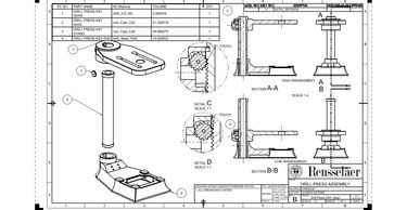
Creating drawings from assembly models is an interesting process in NX as the model can be cut, changed, and exploded to provide a myriad of view points. The drill press assembly challenged my ability to properly lay out and format the press to the given parameters.
Drill Press Assembly
Drill Press Assembly
Drill Press Assembly

The Drill Press Assembly tested my ability to add rotating parts to the assembly and ensure proper movement. My greatest struggle was in constraining the pillar to be stationary instead of the gear. The gear rotated around the about its center axis and the base remained in place due to the overconstrained press bed.
Gyro Assembly
Drill Press Assembly
Drill Press Assembly

The Gyro Assembly introduced aligning curved surfaces. Restricting 360 degree motion in all directions was the most frustrating CAD endeavor I have overcome. In the ball and socket joint, though the model registered the constraint to align the curved surfaces, it would not register the base of the model as solid, so the Gyro was able to rotate freely. This was an issue I had to address with Gyro Base model and how it was exported to the assembly model. In searching for this problem, I was able to explore numerous features of NX related to the theoretical material of the model.
Copyright © 2019 Joseph Vetere Portfolio - All Rights Reserved.